With legalization, comes regulation, and one regulation facing local extractors, is the requirement that they have a certified extraction facility.
To obtain that certification, requires a panoply of steps and maneuvers, including certified extraction equipment, but a subject that comes up regularly, is what is required for a legal extraction booth itself???
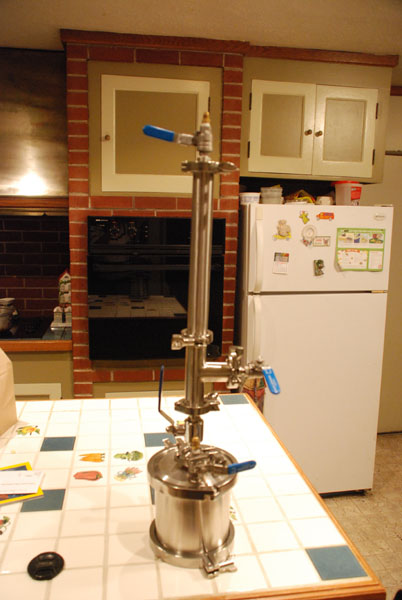
For the moment, I am going to skip over those processes still in use that dump raw butane into the room by open blasting or pouring off early. We will get back to that later as a separate subject, and I will be using a WolfWurx Mk IVC/VC Terpenator™ process, for the purpose of demonstrating intrinsically safe designs.
I picked it because I know it is certified to International Fire Code 2012/2009, ASME Section VIII, Div 1, 2013, and NFPA 58, but as the fish trap exists only because of the fish, there are no issues with other intrinsically safe certified systems being used instead.
I also picked the WW Terpenator™, because it requires no electrical within the room, and thus easily meets NEMA 7, Class I, Div I.
NEMA 7, Class I, Div I standards say that the environment is always explosive, while Class I, Div II standards say that the atmosphere is normally not explosive, but has the potential to be.
While ostensibly even closed loop meeting ASME, yet not meeting NEMA 7 explosion proof standards, is a Class II installation, because they typically don’t leak, O Tooles law tells us that Murphy was an optimist and that things can go wrong, go wrong, go wrong……………
Because LPG is an explosive vapor, going wrong is more serious than more benign gases and vapors, a backup system is required, that eliminates as many of the three requirements for conflagration as possible, which are fuel, oxygen, and ignition source.
A NEMA 7, Class I, Div I extraction enclosure limits ignition sources, and if fuel is present, ventilation can be employed to take advantage of the “dilution solution”, which is to evacuate the leaking LPG at a fast enough rate that it is kept below 10% of Lower Explosive Limits. For butane, LEL is 1.86% and Upper Explosive Limits are 8.41%. Above 8.41%, the mixture of fuel and air containing about 21% oxygen, is too rich to ignite.
Ventilation standards for a Div I room are higher than for a Div II room, because the exhaust must keep ahead of the generation rate to keep the concentration below 10% of Lower Explosion Limits ( LEL), while a Div II room only has to have operator comfort ventilation, and enough air flow to guarantee that a leak is drawn past the HC detector, so as to set off an alarm state.
In alarm state, all room electrical is turned off and additional ventilation is turned on to Div I exhaust standards.
That’s an important factor from an operational and operator comfort standpoint, because what ever amount of air is exhausted, must be made up and if the outside makeup air is too cold or too hot, it has to be tempered.
If we look at the exhaust rates recommended by Industrial Ventilation, A Manual of Recommended Practices, by the American Conference of Governmental Industrial Hygienists, we find Table 4-1 below, which is a table of capture velocity ranges.
Note that the capture velocity standards for a paint spray booth, which is a flammable solvent released at low velocity into moderately still air, calls for 100 to 200 feet per minute air velocity to reliably capture it.
If we look at the bottom of Table 4-1, we note that the lower end of the range more aptly covers our application, so I’ve used 100 surface feet in my designs for Class I, Div I application.
I apologize for the discolored table copies, from the much used pages of my personal “ventilation design bible”, before retirement. I bought the 17th edition new in 1982. If I receive a cease and desist order to remove them from the site, I’ll copy the information into my own tables, but I wanted to add the gravatas of the word from the mountain.
I also wanted to draw everyone’s attention to Industrial Ventilation, which is the bible used in industry to engineer ventilation systems, and the standards that OSHA looks at when evaluating a system.
Like all other industries, commercial cannabis extraction employing others, falls under OSHA’s aegis and their focus is employee safety. They require that you exhaust all engineering avenues to meet employee safety standards, and they use Industrial Ventilation as one of those standards.
It isn’t cheap new , but I’m still using my old 17th edition, which I paid through the nose for originally, but has to be dirt cheeep used on Amazon by now.
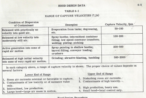
Note that the value expressed in the table is surface feet, not cfm. Cfm is determined by the cross section of the air column you are advancing, times the N surface feet per minute it advances.
Since the measure is surface feet, the amount of exhaust required to meet those requirements would be the height of the booth times it’s width, times 100 surface feet.
Below is a portable booth constructed out of 2 X 2 X 16 ga square tubing, with a 16 gauge metal skin, but the same principles can be employed with metal studs and two layers of 5/8″ dry wall, to achieve a two hour fire barrier.
This booth is 7′ wide X 8′ tall, or 56 square feet face area. Note that I’ve employed 5600 cfm exhaust, to meet the 100 surface feet requirement.
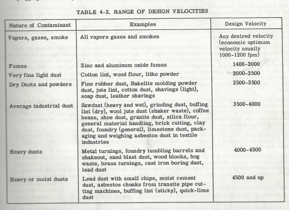
This design uses a full width slot at the bottom of the intake plenum, 9.6 inches tall to achieve 1000 sf slot velocity, to meet Table 4-2 velocity recommendations for transport of vapors, gases, and smoke.
Duct velocities are kept low, to minimize static pressure, and attendant horsepower required, within practical limits on fan size.
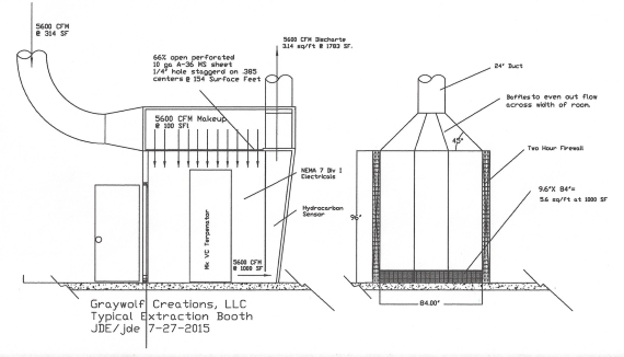
In this design, I made the booth taller and made a plenum by adding a perforated plate ceiling to introduce the air at low velocity and so as to produce as few vagrant air currents as possible, but a simpler design is simply a return air duct, at ceiling height, aimed against the opposite wall from the intake, so it bounces off the wall and sweeps down.
In this design, I also made the booth longer, and canted the back wall to provide space for a front petition, which turns it into an exhaust plenum. That gives me ample space and distance to even out the static pressure across the width of the intake plenum with baffles, while minimizing static pressure losses.
The intake slot in this booth is the width of the booth, and 9.6″ tall, so that its capture velocity at floor level is 1000 surface feet, or 10X minimum, and then we speed it up to 1783 surface feet so permit use of a 24″ spark proof centrifugal blower, with NEMA 7 motor and electrics.
LPG vapors are heavier than air, hence the reason for the intake slot at floor level and the intake coming from above.
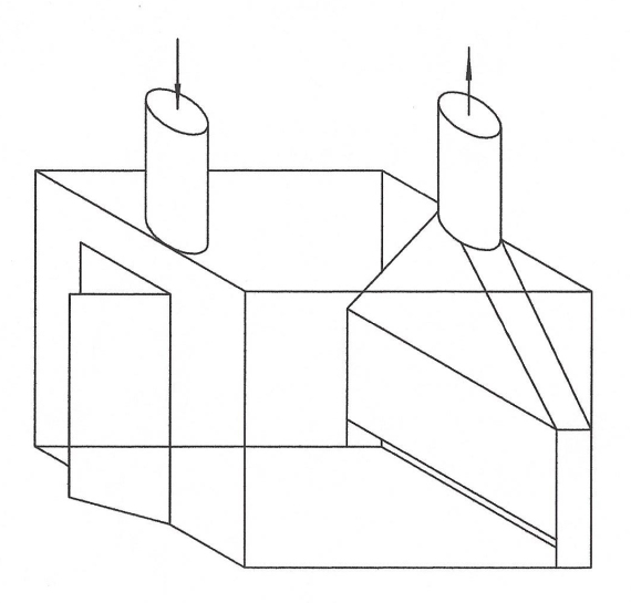
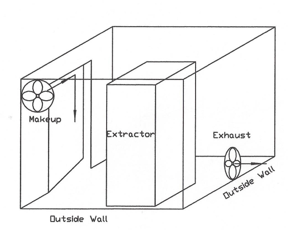
Here are a couple alternate designs. One uses a plenum and slot like the above, and the other is an actual certified installation that I saw in WA, which takes advantage of two outside walls to eliminate ducting static pressure, so as to use axle flow fans.
Back to the discussion regarding intrinsically safe equipment design meeting NEMA 7, Class I, Div I. Below is how WolfWurx achieved it on their Mk IVC
Note that the heating and cooling is supplied from outside the extraction booth, and the equipment in the booth uses no electrical power.
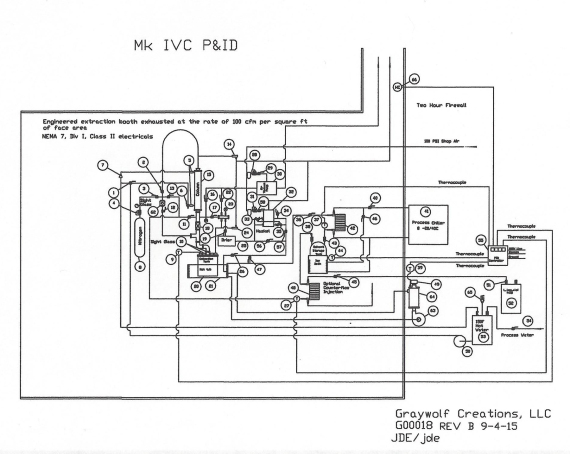
That brings us to the subject of process, which I said that we would return to. There are some key points observed by the WolfWurx Terpenators™, that makes them intrinsically safe to operate.
1.0 The first step is to pressurize the system using N2 and valve off to verify that the system holds pressure.
2.0 If it holds pressure, it is then vacuumed to -29.5″ Hg and valved off to verify that it holds vacuum.
3.0 That step also evacuates the oxygen containing atmosphere from the system, before introducing LPG.
4.0 They inflate the extracted concentrate into foam aka cotton candy, so as to present the thinnest film possible, when purging LPG at high vacuum.
5.0 Both recovery pump and high vacuum pump are pneumatic.
5.1 The vacuum pump discharges directly into ventilation system.
6.0 Columns are baked out at 150F, using a hot water jacket, while under high vacuum, to recover LPG in plant material.
7.0 System is backfilled with N2 to zero gauge, and vacuumed a second time to -29.92″ Hg, where it is backfilled with N2 a second time to zero gauge, or atmospheric pressure.
What the above process does, is insure a sound hermetically sealed system with any oxygen many orders of magnitude below LEL before introducing the LPG.
By purging the LPG from cotton candy foam and baking out the columns at 150F under vacuum, before backfilling with inert N2, then repeating a second time, when the system is opened it is non flammable.
A flame can be held to the spent plant material coming out of the column, and it is no more flammable than virgin material that has yet to be run.
That means that the operator is never exposed to potentially flammable conditions, and the waste products are non hazardous.
Sooooo, what happens when a collection pot is opened early, so as to employ “pour off” techniques?
For starters, at that point even with ventilation, there is a zone within the booth that falls between Lower Explosive Limits, and Upper Explosive Limits.
That means the process relies heavily on no ignition sources, which can be iffy if you take static electricity and sparks into consideration.
Since we are only in control of fuel, oxygen, and ignition sources, with fuel readily available, we can only control the other two variables.
A Class I, Div I room has ostensibly eliminated direct electrical sources and limited static discharges, but it is hard to 100% guarantee the latter and shit happens, so that leaves keeping the oxygen away from the fuel.
I personally use and prefer the cotton candy method, but if I thought that pouring off instead was critical to my process, I would probably build a vacuum or an inert atmosphere chamber to pour off into.
Boiling off under a vacuum or N2 would keep the O2 away, and the discharge from the chamber could be routed to a safe location.


